AIM-TTI | AIM & THURLBY THANDAR INSTRUMENTS
Aim-TTi designs and manufactures advanced electronic test and measurement equipment and laboratory power supplies. Our products are available to purchase throughout the world.PRODUCT SAFETY RECALL QPX750SP Power Supply Serial Numbers 580064 to 585809 - click for details.
POWER SUPPLIES & LOADS

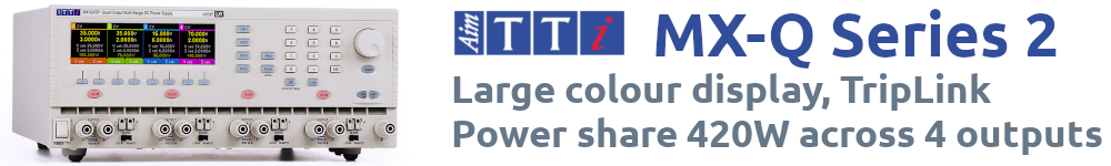
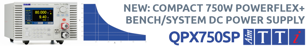
DC Power Supplies
Laboratory power supplies for bench-top or remote control and system use.
Electronic Loads
Flexible electronic DC loads for general purpose applications.PRECISION MEASUREMENT

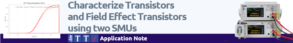
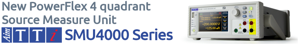
Source Measure Units
High speed precision characterization.
Multimeters
Bench-top digital multimeters for professional applications. High accuracy and resolution.
Frequency Counters
Handheld and bench-top frequency counters up to 6GHz.
LCR Measurement
Precision component measurements
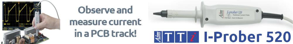
Current Probes
Innovative DC to 5MHz current probes for PCB tracks, component legs etc.WAVEFORM GENERATORS

Function Generators
Analogue and Digital (DDS) function generators with frequencies up to 160MHz.
Pulse Generators
Dedicated pulse generators and function generators with true pulse capability.
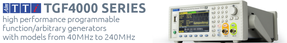
Arbitrary Generators
True variable-clock arbitrary waveform generators, single or dual channel.
Waveform Amplifiers
Used to increase generator output level up to 30V pk-pk.RF & EMC TEST EQUIPMENT

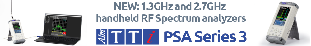
Spectrum Analyzers
Low cost handheld RF spectrum analyzers with bandwidths up to 6GHz.
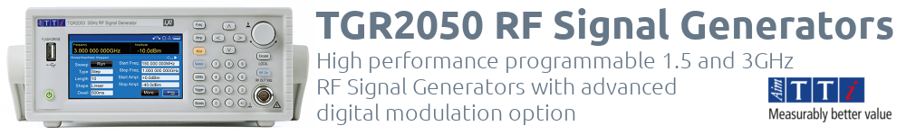
RF Signal Generators
Performance RF generators from 1.0GHz to 6.0GHz
EMC Analyzers
For EMC measurements to EN61000-3-2 and EN61000-3-3.OPTIONS, ACCESSORIES AND SOFTWARE

Product Options: GPIB and software options.
Software Product automation software.